Category Archives: Custom Subassemblies

Custom Subassemblies Lesson 4 – Clever Coding and Variables

Your point/link/shape codes are critical for display purposes in section views etc. Effective code set styles can’t be setup if you have not coded your assembly. But you also need them to be able to generate surfaces, use quantity take off features and generate material take off reports.

If your not sure about point/link/shape codes, read the article here

So you want them to be easy to change, but hard to make a mess on the users side. For this reason, I suggest using the “sandwich” technique. Where every code utilizes the material code (the meat/salad) and has a prefix and a suffix (the bread)

The Prefix
Is generally used for staging/options and for intersection design subassemblies. This allows the user to quickly use the same subassembly twice, but not have the codes muddled because they are the same. So you could put OP1 (option 1) in front of all the codes. Then make an exactly copy of the subassembly change some of the parameters and change the code prefix to OP2 (option 2) and so on. This is a fantastic technique for generating multiple options in the one corridor!

User can specify the prefix for the subassembly
This prefix gets populated to all the codes! Rather than typing them one by one!

The suffix
Is used to denote the components of the subassembly. So DL = Daylight Point, CR = Crest Point, Top = Top Links. These are all common between the materials.

The Result
Is you end up getting a logical list like so

OP1_A_CR – point code
OP1_A_DL
OP1_A_Top – link code
OP1_A_Bot
OP1_B_CR
OP1_B_DL
Etc. etc.

Which makes life very easy

Setting up in Subassembly Composer
1. Start every CS by adding in these two flow charts first
image004image005

–  Variables will contain parameters that are common throughout the CS. So things like “Delta X for Layout” or “Depth for Layout”, the length used to display surface links on you’re assembly
–  Codes will be used to create all the ‘sandwiches” you need to code your subassembly effectively.

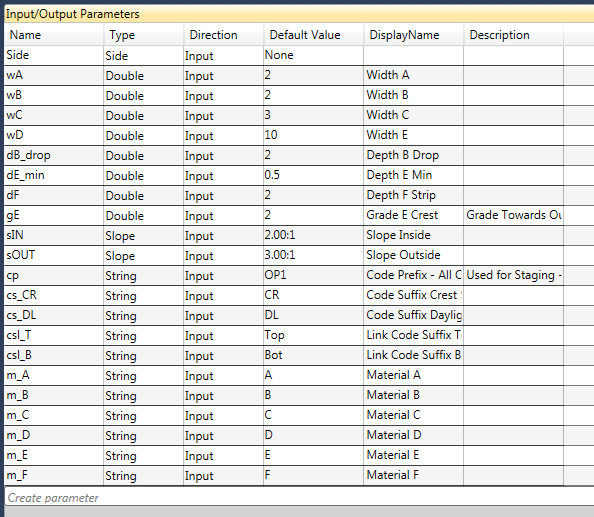
2. Double click the Variables Flow chart and begin by creating a zDFL as per below

Rather than typing the default value as 20, you could link this to an input parameter. Which means the user could control the “depth for layout” or how high the section looks when you attach it to an assembly in C3D.

3. Now go into the Codes Chart, in here we are going to create all the code pairs “sandwiches” that we will need. Lets consider Material D.

In material D we will have two surfaces (orange and red) that can be created. Top and Bottom (from 4 links), 4 Feature lines and 1 Shape Code, So:

Points
OP1_D_DL x 2 (its important to have only 2 feature lines created at either edge of a series of links, this way boundaries can be specified automatically)
OP1_D_CR x 2

Links
OP1_D_Top
OP1_D_Bot

Shape Codes
OP1_D (no need for suffixes here as we only have one material)

Shared Links and Points
Of course some of our links will share links with another material, like C and D and E and D, likewise with points. So how do we handle this confusion?

By systematically going through the materials we can create the variables quite quickly. You could do this by typing into each link/point. But I prefer to sort it all out in the codes flowchart then link the result back to the link/points at the end.

Starting with Material D you can define variables (you can start with A if you want!

Variable Code Result
pD_DL = cp +m_D + cs_DL OP1_D_DL
pD_CR_1 = cp + m_D + cs_CR + “,” + cp + m_C + cs_DL OP1_D_CR,OP1_C_DL
pD_CR_2 = cp + m_D + cs_CR + “,” + cp + m_E + cs_DL OP1_D_CR,OP1_E_DL
lD_Top_1 = cp + m_D + csl_T + “,” + cp + m_C + csl_B OP1_D_top,OP1_C_bot
lD_Top_2 = cp + m_D + csl_T + “,” + cp + m_E + csl_B OP1_D_top,OP1_E_bot
lD_Top_3 = cp + m_D + csl_T + “,” + cp + csl_T + “,” + cp + “SlopeOut” OP1_D_top,OP1_Top,OP1_SlopeOut
lD_Bot = cp + m_D + csl_B + “,” + cp + m_F + csl_B OP1_D_bot,OP1_F_top
pC_DL = …. Etc. etc..

Then systematically working through by material you will eventually have all these parameters you can call rather quickly. Making it a lot easier to code, as well as understand for the end user of the CS.

Go through and create the rest. then move on to %Lesson 5%

Loading

Custom Subassemblies Lesson 3 – Adding your Parameters

For the next few lessons I will continue developing the dam section shown in Lesson 2.

So open Subassembly Composer – Start Menu -> search “Sub” You should see it

Before you do anything chose a good place to save all your subassemblies. I prefer to keep them in one place in a development folder. Then copy them to the project standard folder if that project utilizes that particular subassembly.

1. Save to your development folder “DamAssembly”

2. Now input all your input parameters you will need. Remember, try to group them by widths/grades/slopes etc (there are no sorting buttons, however if you are really deep in and don’t want to delete and recreate, here is a workaround you can use to sort the parameters without deleting them)

3. Set the Type, Double (Decimal Numbers), Integer (Whole Numbers), String (Text), Slope/grade etc.

4. Set a good default value for the parameters and use a logical display name that will make sense to the end user.

5. Lastly Pick a Side. If you don’t pick a side you can’t use the mirror functionality to quickly flip the subassembly to operate the other way

inputparameters
Remember to group your parameters by width/slope/grade etc. to make it easy for the end user

One thing you will notice is I have not created every code in the subassembly. Just parts that can be combined together to form the finished code. I.E – for material A top links it will be <cp + m_A + csl_T> or OP1_A_top

This is my complete Target Parameters Table

6. Now input all your target parameters you will need. Remember, try to group them by offsets, elevations, surfaces etc.

So a curious thing you will notice is the sl_IN, sl_OUT, dp_B are all linked to elevation type. This is because I am going to use a elevation profile to control the parameter. So I can create smooth transitions. This is explained in more detail in %Profile Based Parameters%

Now on to Lesson 4 – Clever Coding

Loading

Custom Subassemblies Lesson 2 – Plan your functionality

Onwards to development comrades…

The best results often reside in good planning, custom subassemblies are no exception to this. However, if you are reading this you are probably not entirely sure what the best result is going to be.

So here is a process/guide to developing a good CS:

· Start by drawing a cross section of the most typical arrangement. (You may need to draw multiple sections for varying scenarios if they are complex)
Then consider the following

· All the parameters you wish to be able to specify. Width, Depths, Grades, Slopes, Elevations. (Group your parameters using these categories, it makes it simpler to find the correct parameters for the end user)

· Where your centerline will be horizontally, i.e the assembly point. Placing this in the middle of your CS might not always be the best idea. Likewise, using a daylight is not usually a good idea. Typically pick the most fixed point possible on your subassembly. Its also important to consider if your alignment will have sharp curves, picking a point on that will be on the inner part of the curve may help.

· Consider all the surfaces that will be involved in determining the finished geometry. Typically this is only one (Existing Ground/Survey). Try to avoid having more than one if possible, i.e using dummy surfaces. Quite often there are simpler ways to calculate your geometry.

· Next consider the parameters you wish to override using either offsets alignments (width targets) / profiles or 3d linework (elevation targets).

· Next consider if you want to control these parameters by specifying absolute value/relative value. See my article here to understand this concept

· Lastly, consider your point/link/shapes codes. I suggest working in the reverse order though. Determine your materials (shape codes), then derive your point and links codes from these names. As explained in the %Coding your point/link/shape codes lesson% it is easier to just have the user type the material names and have everything else worked out based on these names.

You should end up with something that looks a little like below.

This is merely a guide to planning, but it will help you a lot to layout your plan before you start creating anything. Particular for more complex subassemblies.

Loading

Custom Subassemblies Lesson 1 – Do I even need a custom subassembly?

You might be already well aware you need a custom subassembly (CS) because things are getting hectic, so you can skip this article

It is always a good idea to stop and determine “if I even need to” though. So, if you’re not sure, here are some general rules of thumb to follow to determine if you need a CS.

You should create a CS if:-

1. Your Corridor Model requires you to transition daylight slopes smoothly over distance. I.E 1:2 up to 1:6 and back to 1:2 over specified distances

2. Your corridor model has a complicated target list, say 5 or more targets you need to specify. Particularly elevation/grade targets. These can take longer to manage as they are usually all different targets, unlike surfaces which are typically all just EG and can be set all at once.

This list can grow long very quickly! Particularly when you start changing the targets between regions etc.

3. Managing your codes (point/link/shape) is becoming difficult to manage

4. You want to develop multiple stages to calculate volumes over time. Similar to above.

5. You wish to calculate internal materials that differ from the generic/road based subassemblies provided by the software. (plus making surfaces is difficult due to differing boundary conditions)

These are a few good signs that creating a CS will benefit you. However as an umbrella rule,

if it is taking too much time….. take some time… to create a CS.

Loading