Tag Archives: stage storage

Stage Storage Analysis of Stockpiles/Dam Walls (between two irregular surfaces)

UPDATE: You can do this even easier with the “Stage Storage Basin Tool” available in my free tools package here
https://ceethreedee.com/ceethreedee-tools

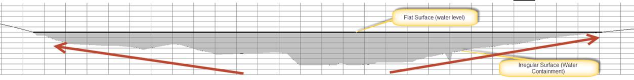
It is quite easy to do perform a stage storage analysis of a simple basin or dam water. This is because all the volumes are compared to a flat elevation, one flat surface (water level), one irregular surface(ground surface).

But what if you want to know the stage storage elevation of a dam wall or a stockpile, i.e two irregular surfaces).

Well you can essentially use the same technique as described here, but you will need to compare the two stage storage analysis’s to get the final answer.

Keep reading to find out how or if your feeling lazy watch the video here.

Basin Stage Storage (Flat to Irregular)

image004

Stockpile Stage Storage (Irregular to Irregular)

image006

By turning our two irregular surfaces into two separate stage storage calculations to a common flat surface, we can then subtract one from the other to form a stage storage of the stockpile.
image009

Firstly we need to create the common flat surface, the best technique is to find the Max RL of the design surface, by looking at the Surface Properties.

image013

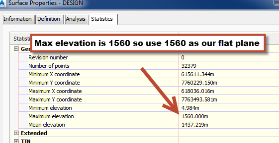
On this stockpile the max RL is 1560 . So, I’m going to create a flat plane at 1560 m and add it to a new surface called “CALC LEVEL”

image019

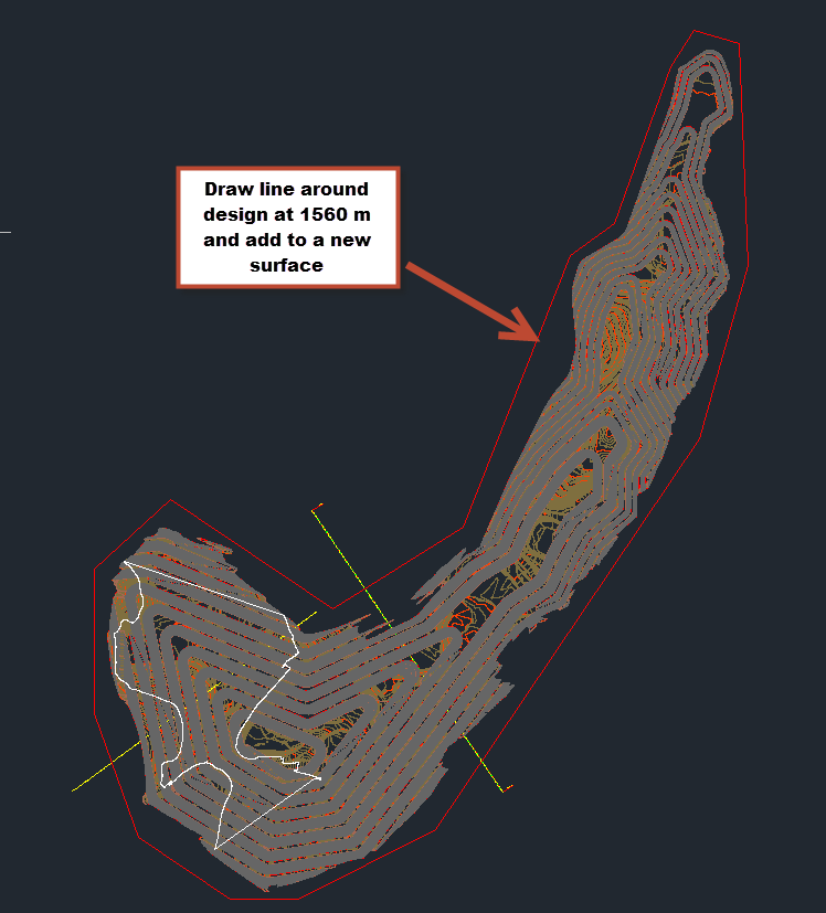
Now we need to limit our calculation to the design extent
image021

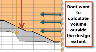
So you will need to create a surface that clips the existing ground to the design surface boundary.
image014

Now you have all the surfaces you need, you can create the two volume surfaces to do the stage storage,

  • one that compares to the design, – The Subtract Surface
  • and another that compares to the existing ground – The Addition Surface

image023

Extract the stage storages for both of them using the technique described in my post here

image016

You will now need to do a simple subtraction between the two stage storages to form a combined stage storage like below.
image017

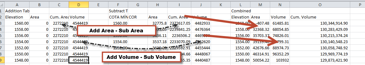
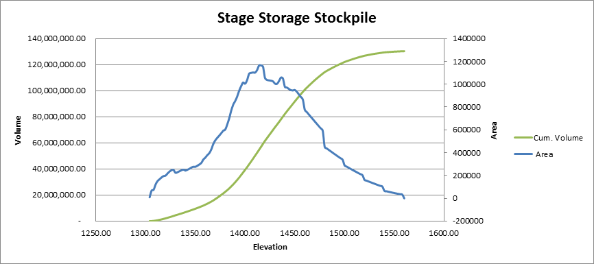
The finished result it is quite clear. Looking at the area it starts narrow at the bottom, increases to full width where the toe meets the ground, then reduces in size as it goes back down to the crest of the stockpile. The change in volume also reflects with the increase in area.

image020

Do a final check with a volume surface at the end to see if your correct.

Loading

Alternative Stage Storage Technique – Civil 3D Tables

UPDATE 2: My new tool complete obsoletes this process.. Stage storage basin tool is available in my free tools package here
https://ceethreedee.com/ceethreedee-tools

UPDATE: Feeling Lazy. Watch the Video.

This deals with basic “basin” stage storage calculations. For more complex stockpiles etc. Read this post here

Download lisp file from this link download COT

UPDATE: instead of using COT.lsp. Try the free “Table Exporter” App from the autodesk exchange from here. Only works in 2015 unfortunately 🙁

It will dump what ever table you select straight to excel though..
exporttable1exporttable3

I see a lot of people still using this outdated tool in Civil 3D for calculating stage storage! For those who calculate stage storages read below!

Please stop using it! Although it is possible to get a relatively accurate result from it. There are a number of problems that I will merely bullet point below.

  • Can only have one contour at each level to get stage storage curve. (although you can sum them together in excel)
  • If contours are not closed this can create errors in the calculation.
  • Multiple islands and “flat areas” (i.e benching) can be easily miscalculated. Who has benching in their designs! :p
  • Higher Intervals reduces accuracy!
  • Not to mention it is cumbersome!

Civil 3D has always had the ability to do accurate stage storages, I will demonstrate below. (*with the assistance of a lisp!)

Download lisp file from this link download COT

1. Create a Volume Surface comparing Water Level or Final Tailings level etc. and your completed design. (Yes you can calculate tailings stages as well!)

2. Drop down elevations in the analysis tab at the intervals you wish to calculate your volumes at. (use Range Interval with Datum)

3. Create a surface legend table that includes “Surface Range volume” and Surface Range 2d area)
SurfaceAreaVolume

4. Copy table to left or right and explode twice, then use the attached lisp routine to convert to an autocad table.

5. Export Table to CSV as shown above and then open in excel. You will need to sum the areas and volumes from the bottom up to get the correct results.

Finished Result, sum up the volumes from the lowest elevation, (so the bottom up). or reverse the order and sum them from the top down..

Elevation (m) Plan Area (m²) Cum. Area (m²) Volume (m³) Cum. Volume (m³)
102 5,872 143,202 280,514 1,432,735
100 5,751 137,330 268,936 1,152,221
98 5,969 131,578 257,244 883,285
96 13,903 125,609 240,933 626,041
94 26,862 111,706 200,242 385,108
92 42,463 84,845 126,689 184,866
90 31,232 42,382 51,424 58,177
88 11,149 11,150 6,752 6,753
86 1 1 1 1

You will notice that unlike the old stage storage tool that can vary in accuracy especially with larger intervals. This method is exactly right down to the triangle.

Comment below if you want to know more

Loading