We are often exporting volumes from our models and for a lot of designers and drafters it is an adhoc affair. Engineer asks for volumes, so you make a few volume surfaces quickly, export volumes into excel, format a bit and then send. Some of the slightly more organized types might even save the excel spreadsheet into their modelling folder in case they need to use it again! But more often than not you will be asked to do this several times over the life of the project. So why not come up with a decent system for handling this process?
I would like to present a more efficient method, that not only is easy to update and manage but will improve the performance of your modelling files as well.
The workflow is quite simple, it may take slightly longer to setup. But I promise, you will thank yourself later. They key element been the use of the volumes dashboard.
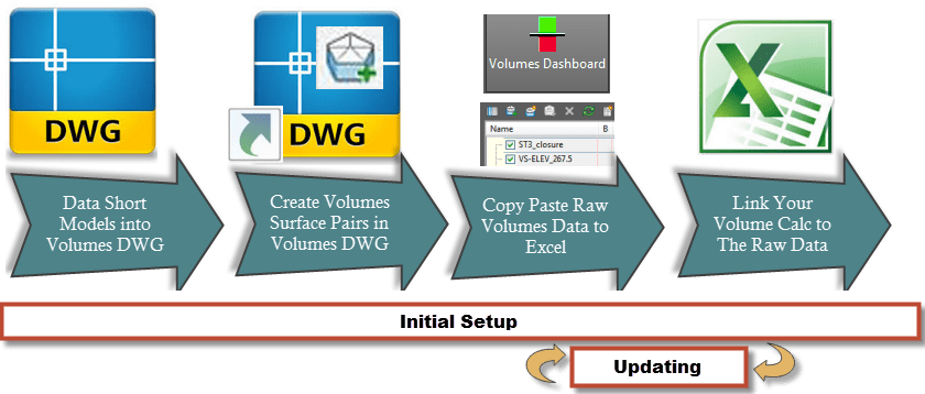
A few simple rules to follow to ensure you maintain a nice link.
1. Never create all your volumes in the modelling DWG. Create them all in a separate DWG using data shortcuted surfaces (The odd one is fine).
2. Don’t manipulate the raw data you copy from the volumes dashboard (other than a sort). Link to it from another table in excel.
3. Don’t “Cut data over”/ Copy Data over the top in excel. Otherwise your links break!
Volume surfaces quickly increase the size of modelling dwg’s and will decrease overall performance when working in them. Unless you don’t work in your modelling DWG’s very often, which I highly doubt, keep your volumes surface in a separate dwg and data shortcut all the surfaces you need in. This also makes it easier to extract all the volumes you need in one hit rather then prowling around your dwg’s looking for quantities.
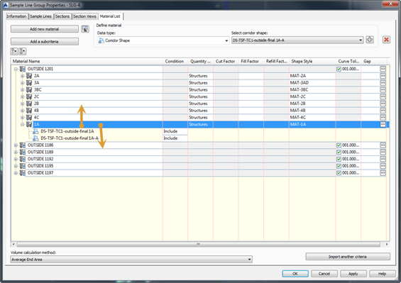
Once you have created your volumes DWG and you have data shortcutted the surfaces you need in. Start creating Volumes Surface Pairs. I strongly suggest maintaining a simple but consistent naming system. My system is as follows
<identifiers>-<object>_<material_name>
So for example:
OP2-NTH-ROAD_gravel
OP2-NTH-ROAD_base
OP2-NTH-ROAD_ subbase etc..
This makes your life a lot easier when creating links in excel. It also helps prevent the desire to shoot yourself due to confusion later on :p.
Now you have pairs, it’s time to setup an excel file. My pairs looks like so:

Right Click on any surface in the dashboard to “Copy to Clipboard”
Open Excel, an begin by creating two tabs “Volumes”,”Data”. Data is where we will copy the raw data from your volumes dashboard (copy your raw output now). Volumes is where we will create the links to the volumes dashboard data so it is easier to update later.

Your data is now on the data tab. Do a sort on it (Volumes Dashboard doesn’t have a sort function!)
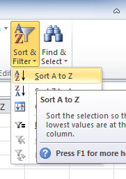
Your data should sort by surface name! This will save headaches later when you want to update the table or add new surfaces.

Now switch over to the Volumes tab and start creating a table like the one below. With various identifiers you need for each material volume you want to calculate. In the last column (2nd last in my case) you want to link the QTY back to the “data” tab that contains your raw pasted volumes dashboard data.
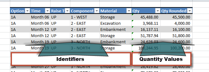
Now this table you create will eventually contain all the volumes you want, but not exactly in the best format for visualizing. This last step can be quite confusing for a lot of people. So hopefully the video link at the top helps.
Because the table is arranged in a “basic record format” like Microsoft Access or any SQL etc. we can use this table to create “Pivot Tables” and “Pivot Charts”.
Firstly covert your table into a “Named Range” by using the format as table function
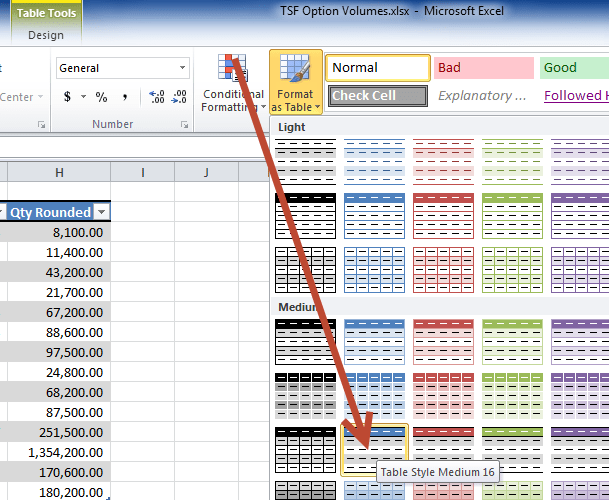
Now select anywhere in your nicely formatted table and go to Insert -> Pivottable.

You will be confronted with a blank screen and most likely see all your column headers on the right.
By drag-droping your tables headers into the fields as required you can make your table display exactly as you need it. (I highly suggest watching the video to see this in action)
But for example say I wanted a table to display the materials as the column headers, the time as rows and calculate the quantities with respect to these columns. I could do the following
 Then you will get this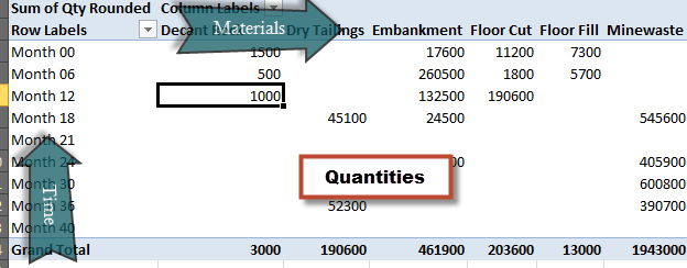
But you can adjust these to suit your needs. Better, you can adjust to suit other people’s needs. You can create as many pivot tables as you want to display different views of your data and they are all stay linked back to the original source..
Now when it comes time to update your volumes from Civil 3D all you have to do is copy your volumes dashboard output… sort and paste over the top in your data tab!

The end result wonderfully formatted, dynamic tables. That can update almost at the click of a button…
| Component | Time-Height | Embankment | Storage | Decant Rock | Floor Cut | Floor Fill | Wall Excavate | Windrows | Minewaste | Dry Tailings |
| 3 – NORTH | Month 00 – 487.82 m – DOWN | 16,600 | 500 | 5,900 | 5,200 | 6,100 | 500 | |||
| Month 06 – 487.82 m – DOWN | 39,900 | 500 | ||||||||
| Month 06 – 489.92 m – DOWN | 27,700 | 500 | ||||||||
| Month 12 – 493.02 m – DOWN | 116,500 | 60,800 | 1,000 | 600 | ||||||
| Month 21 – 493.02 m – DOWN | 101,500 | |||||||||
| 3 – NORTH Total | 160,800 | 102,200 | 2,000 | 5,900 | 5,200 | 6,100 | 1,600 | |||
| 4 – SOUTHEAST | Month 06 – 489 m – DOWN | 125,100 | 600 | |||||||
| Month 18 – 489 m – DOWN | 325,100 | |||||||||
| 4 – SOUTHEAST Total | 125,100 | 325,100 | 600 | |||||||
| 5 – MINEWASTE | Month 18 – 497.7 m – DOWN | 545,600 | ||||||||
| Month 24 – 497.7 m – STACK | 405,900 | |||||||||
| Month 30 – 497.7 m – STACK | 600,800 | |||||||||
| Month 36 – 497.7 m – STACK | 390,700 | |||||||||
| 5 – MINEWASTE Total | 1,943,000 | |||||||||
| 6 – DRY STACK | Month 12 – 485.2 m – STACK | 190,600 | ||||||||
| Month 18 – 485.2 m – STACK | 45,100 | |||||||||
| Month 24 – 487 m – STACK | 47,200 | |||||||||
| Month 30 – 489 m – STACK | 46,000 | |||||||||
| Month 36 – 491.8 m – STACK | 52,300 | |||||||||
| 6 – DRY STACK Total | 190,600 | 190,600 | ||||||||
| Grand Total | 285,900 | 527,300 | 2,000 | 196,500 | 5,200 | 6,100 | 2,200 | 1,943,000 | 190,600 |