The horizontal geometry band displays no values until the alignment is promoted. Breaking the reference to our alignment, which is not a suitable workaround IMO as we have too many profile views, alignments that would need to be recreated if something changes…
We really need a proper fix for this ASAP.
Before no values displayed
After, promoting the alignment, removing the band and re-adding ,the values now display.. (not a suitable workaround!)
UPDATE: Autodesk is aware of this issue and can reproduce the problem CaseNo:10466148, This only happens when you ahve your properties palette open.
This is a difficult one to explain. So I have made a screencast to show you here
But basically when selecting something that is a civil 3d object with a “Left-Right” or “right-left” selection and you drag your mouse outside the autocad window (say the start menu). Autocad no longer is the current program. Requiring the user to select the autocad icon on start menu. Or click on the top bar to regain focus..
Very frustrating as my commands often have to be done twice as a result. OR more often then not a complicated selection during a command that may have taken a little while is lost.
Additionally once this has occurred once. A left-right selection on the object without even dragging outside will continue to allow the program to lose focus!
See example file and explanation below so you can recreate problem for yourselves.
Well after some basic investigation I have found the problem.
Overlapping surfaces that both have contours displayed will cause freezing when osnaps is turned on.
Download the example file here – onsnaps-freeze1, see image below for explanation. Try and draw a polyline over the top of the overlapping area with onsnaps turned on
I can confirm that this happens in both Civil 3D 2014 and 2015. With 2015 recovering slighltly faster than 2014. say 3-5 minutes instead of 10 – 15minutes
See my previous post here to see the full process. This is an expansion on this process to bring in more or better quality imagery.
Once you have setup your coord system etc. as per previous post, you then want to zoom your screen down to the desired resolution. I find going one zoom level further in than you like is usually a good strategy.
Now you want to keep pressing “save as image” then panning your screen around to get the tiles you desire. Just use your middle mouse button, don’t zoom in and out. Give the images about 5/10% overlap.
Once you have saved all the images you need. Just read them back in to have a look at the finished result. I have saved 6 images below.
Now I want to merge them together as one image.
Raster -> Miscellaneous -> Merge
So now you just need to output your merged image in the desired coordinate system.
Right click the layer and press “save as”
Make sure you tick “rendered Image” and specify your desired coord system.
Give it a short moment to output
Now read into cad. Don’t forget to set your units to “meters” on command INSUNITS if you are using the metric system.
You should now have an image in CAD that is better resolution, or covers a more vast area
A common problem with Civil 3D. If you have a surface with a hole, the hole will not be filled with the surface you are pasting into. It will triangular across the hole like below.
Pond with hole in middle
Pond design with hole in the middle
When pasted together the middle is wiped out. Rather than the middle been taken by the existing surface pasted in first.
Pasting together removes the first surface definition and creates and empty space
I know you can create a “hole surface” as workaround, but this isn’t as dynamic.
Q: Thanks Brad. Looks like a good solution for this scenario where the spigots are in a straight line, but how would you go about doing a perimeter discharge (the most common type of TSF). The pathways and guidelines would be crossing over.
A: It’s a good question, I generally wanted to just show the basic concept in the original post. To do a perimeter discharge you just draw pathways coming back the other way and very roughly trim them up.
Here is how I would tackle it using the same method.
I start by making the one spigot discharge into a block. Then use the measure command to space it around the complex at 200m intervals. Align that block to the line and you get something like below.
permiter deposition
I delete a few of the stranger spigots, relocate as necessary then I just keep trimming the lines inside the block until I get to a point where I don’t have too much overlap. Like below. (If I trim in the block, they all change at once. J)
Perimeter Tailings Deposition, trim up block lines before exploding
Trim any major areas of overlap and then check your rough triangles surface, near enough is good enough here, minor overlap will be taken care of by the kriging routine,
Perimeter Tailings Deposition, check result in basic triangulation
This is what we want to achieve (below). A tailing’s deposition that looks realistic, showing flow originating from each point (a spigot) at a specified grade(s) outwards until it is bound by the existing ground or a designed embankment.
But how can we do this quickly without software like Muck 3D and Vulcan?
The method described below in no way replaces these fantastic tools completely, Particularly when creating vast amounts of options/beach slopes etc. But it does produce a realistic result that is very easy to update. Read on to see how I do it. (P.S It’s not the concentric circles technique!)
So here is the general plan before we knew where anything was…
First I determined an approximate spigot spacing with the engineers and then chose a suitable elevation to deposit from. You can work this out with some rough calcs.
(<Change in elevation> * <2d Area>) / 3 – Note: keep adjusting the elevation to gain more/less volume
(20 * 331000)/3 – 2.2Mm³ so if I deposit from about 274 should be approx. right. (it’s easy to adjust later)
Create a base pathway using a 3D poly line (command 3DPOLY)
Engineers have told me they want a 200m spigot spacing, 3 spigots. So offset some 100m guidelines either side of your main deposition path
Draw 3 more path ways on one side of the deposition, a ¾ length a ¼ length and back trail
Now you need to grade all of your lines to your desired tailings beach. Engineers have told me that we can achieve a 0.5% beach slope.
Select start point, type starting elevation, select to the end and type grade on all lines.
Then just mirror them across to other side and delete your guide lines. You should end up with something like below. (copy this off to the side somewhere if you want to change the beach grade later)
Copy the pathways to your spigot locations and rotate as necessary. Then draw some trail lines on the wings. Put all those deposition lines on their own layer and you should end up with something like below.
It’s okay to have a little bit of overlap, but try to avoid it if possible!
Now add these as breaklines to a surface called TS-TAILS_<some description>
Check for any strange anomalies in elevation first. Then you want to run a krig on the surface.
Go to the surface definition and right click on edits -> smooth surface
Change to Kriging and then select parameters as defined in image.
The finished result. Is obviously exactly what you are looking for. Now you just need to create a design embankment to entrap the tailings
If you zoom into the tailings surface where one of the contours meets a break line. You will notice some little spikes. These may be more pronounced on your model.
To fix this issue simply tick off the breaklines from the definition under surface properties.
Once you have designed an embankments to suit your deposition. Just find the intersection between your tailings TS surface and your CP combined natural and embankment
Some Notes
· To vary the deposition height, raise lower the TS surface, or relocate/raise/lower the breaklines.
· If you want to change the grade of the deposition, you will need to regrade all the lines, you don’t have to delete them though. (A good trick is to keep a block that represents one spigot and just regrade that and copy it around.)
· Always keep an unclipped (TS surface) and a clipped (DS surface) so if your design updates it’s easy to recreate a boundary.
· Do all your tailings modelling in a separate dwg file!
· Kriging does not update if you change the breaklines, so try to do all your editing to your pathways pre-kriging then run the krig at the end
This is just a basic example, there are obviously more complex scenarios, like multiple elevation spigot points and bimodal (multiple grade) tailings beaches. But I hope to cover these in a later post.
You may also notice the benefits of kriging for things like groundwater modelling/geological surfaces and air pollution modelling.
Reply to this email if you have any questions, or post on the 3D forum.
For the next few lessons I will continue developing the dam section shown in Lesson 2.
So open Subassembly Composer – Start Menu -> search “Sub” You should see it
Before you do anything chose a good place to save all your subassemblies. I prefer to keep them in one place in a development folder. Then copy them to the project standard folder if that project utilizes that particular subassembly.
1. Save to your development folder “DamAssembly”
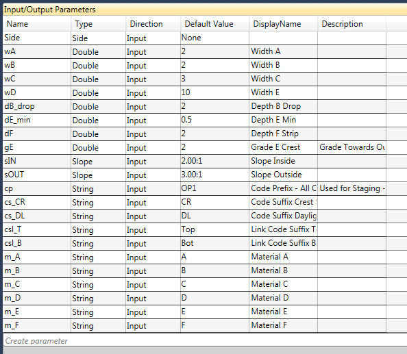
2. Now input all your input parameters you will need. Remember, try to group them by widths/grades/slopes etc (there are no sorting buttons, however if you are really deep in and don’t want to delete and recreate, here is a workaround you can use to sort the parameters without deleting them)
3. Set the Type, Double (Decimal Numbers), Integer (Whole Numbers), String (Text), Slope/grade etc.
4. Set a good default value for the parameters and use a logical display name that will make sense to the end user.
5. Lastly Pick a Side. If you don’t pick a side you can’t use the mirror functionality to quickly flip the subassembly to operate the other way
Remember to group your parameters by width/slope/grade etc. to make it easy for the end user
One thing you will notice is I have not created every code in the subassembly. Just parts that can be combined together to form the finished code. I.E – for material A top links it will be <cp + m_A + csl_T> or OP1_A_top
This is my complete Target Parameters Table
6. Now input all your target parameters you will need. Remember, try to group them by offsets, elevations, surfaces etc.
So a curious thing you will notice is the sl_IN, sl_OUT, dp_B are all linked to elevation type. This is because I am going to use a elevation profile to control the parameter. So I can create smooth transitions. This is explained in more detail in %Profile Based Parameters%
This is the free option for those of you looking to get some public imagery into cad. Although I imagine if you are using Civil 3D 2015 with the new bing maps functionality. This method is a little defunct. If your using Vanilla Autocad you will need to download the GEOREFIMG lisp from CAD Studio to import
Feeling Lazy… Watch the video
QGIS or Quantum GIS has much more functionality than just saving Aerial Imagery. It’s a very comprehensive and powerful free GIS tool that should be in every designers arsenal.
1. Next open up QGIS from the desktop shortcut (im using 2.8.3 Wien when writing this)
2. Go to Plugins – > Manage and Install Plugins
3. Search for the OpenLayers Plugin and Install
4. Next we need some data to quickly get your location correct. Export either a 2007 DXF or MAPEXPORT a SHP file that contains some line work of your area that’s in a known coordinate system.
5. You can either drag drop it into QGIS or just press the “Import Vector Data button”
6. QGIS should prompt you for a coordinate system for your data. If it doesnt, right Click on the layer in the layers window on the left and select “Set Layer CRS”
7. Im in Australia so I select MGA zone 56. QGIS’s coordinate system library is incredibly comprehensive so you shouldn’t have any problems finding yours here.
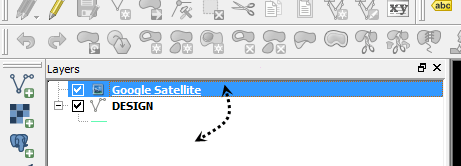
8. Now the imagery, go to Web -> OpenLayers plugin -> pick a imagery source. Google/Bing/Yahoo/OSM/Apple street and aerial/hybrid sources are available
9. You should now have imagery in. You might need to change the draw order to check that your line work matches up, drag drop them so that your line work is on top.
Imagery in
10. Now just get your viewport to the imagery extents you want, then turn off the linework. The image will save whatever you are looking at, in whatever coordinate system you have specified for the project.
The resolution will be what you see is what you get (WYSIWYG) so if you want a better resolution you will need to save multiple images at a closer view. See my post here on how to do that, or watch the video above.
11. Now save your image. Go to Project -> “Save As Image” and call it “Google-PSY” the PSY indicates it is in the WGS84 Pseudo Mercator Coordinate system.
12. We now need to read the saved image back in and convert it to the correct coordinate system been – MGA zone 55. Using the Warp (Reproject) from the Raster-> Projections menu.
13. Specify the “Google-PSY.png” we saved, choose the output file, Make sure you specify the source coordinate system (WGS84 – Psuedo Mercator) and the target coord system (mine is MGA zone 55)
14. Export it as a “Geotiff” and call it Google-MGA55 or whatever your coordinate system is. The Geotiff format will contain all the georeferencing information inside the file.
15. Now just use MAPIINSERT command (GEOREFIMG lisp for vanilla cad users) to import into CAD. Pow! Imagery. This also works well for stitching bits of imagery together.
You might be already well aware you need a custom subassembly (CS) because things are getting hectic, so you can skip this article
It is always a good idea to stop and determine “if I even need to” though. So, if you’re not sure, here are some general rules of thumb to follow to determine if you need a CS.
You should create a CS if:-
1. Your Corridor Model requires you to transition daylight slopes smoothly over distance. I.E 1:2 up to 1:6 and back to 1:2 over specified distances
2. Your corridor model has a complicated target list, say 5 or more targets you need to specify. Particularly elevation/grade targets. These can take longer to manage as they are usually all different targets, unlike surfaces which are typically all just EG and can be set all at once.
This list can grow long very quickly! Particularly when you start changing the targets between regions etc.
3. Managing your codes (point/link/shape) is becoming difficult to manage
4. You want to develop multiple stages to calculate volumes over time. Similar to above.
5. You wish to calculate internal materials that differ from the generic/road based subassemblies provided by the software. (plus making surfaces is difficult due to differing boundary conditions)
These are a few good signs that creating a CS will benefit you. However as an umbrella rule,
if it is taking too much time….. take some time… to create a CS.
Civil 3D news/tips/tricks from someone like you and also some Unity Game Development stuff