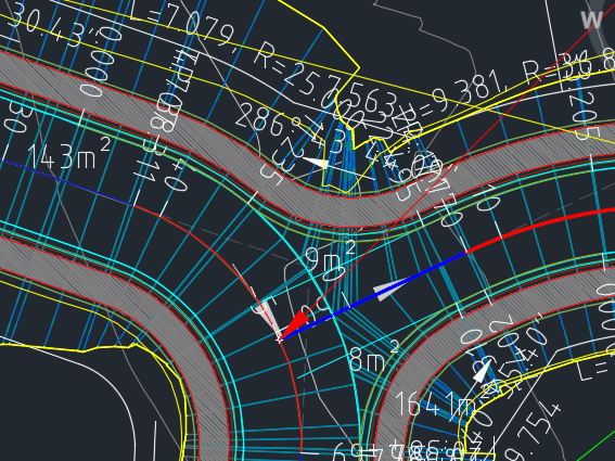
I think it’s safe to say that the intersection object (that is not really an object) and the wizard that creates them are from a different age, they are dinosaurs that should have died a long time ago.
Check out 12D’s “Create Roads” functionality. It creates “multiple intersections” at once, as well as creating the cul-de-sacs automatically. Why can’t civil 3d leave the dark ages and develop some functionality like this?
When using Plan Production Tools. Pipe network styles and labels in plan view do not get carried through to the new drawing. It simply defaults back to the default styles in command settings.
Can we please add a way to use the styles and profile labels specified in the drawing that we create the sheets from. Particularly on larger projects, its really annoying to have to open all the sheets a respecify all the labels we already specified.
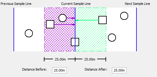
Projection sets would allow you to create a dynamic editable “query” to group desired objects that you want to use for projection. This query also defines how these objects should be displayed in profile/section views/exaggerated views?.
I’ll let the image below explain itself. But generally a few key points.
ALL Objects are Available for Projection!!!
ALL Objects can be assigned labels as well as projections styles
BOTH Profile Views/Sections views have similar projection options (Crossing/Superimposed/Bounding Box limit etc, explained further below)
Queries can be assigned to objects so that they can be assigned default styles based on the point group or there layer or whatever.
The same projection set can be used for multiple profile views etc.. Its dynamic..When it updates it updates the profile view/section nview etc.
Projection Options/Types
It’s really important that we have options to filter how objects are selected/cut/displayed in section/profile views.
I’m thinking there could be two/three types.
These would be saved as styles and can be changed/updated.
Crossing Only Only objects that intersect the line are displayed
Bounded Parameters Only objects within specified parameters can be seen. I.E 25m either side of alignment. Similar to how the sample line projections work now. This should be enabled for profiles views as well of course!
Bounded Objec Only objects within a selected polygon are sampled. This would allow flexibility for users to limit things by stage boundaries etc..
Anyone who is new or old to Civil 3D knows how difficult it is to create all the styles you will need to finish projects in a timely fashion. But most of us don’t have the time to sit down and create all these styles. Let alone the will power to just sit down and create styles and nothing else.
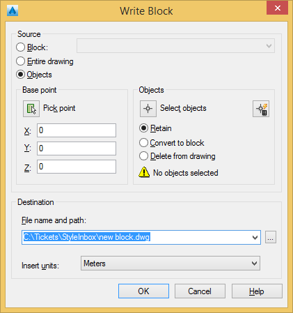
So here is a technique for creating styles as you do project work. Using a WBLOCK style inbox.
Feeling lazy.. watch the video.
In a nut shell though, you are working, you create a style. You WBLOCK it out to a common directory. You keep working.
Next chance you get some free time you do some “Style Review and Cleanup”. Incorporate it back into your template. Then Repeat!
The WBLOCK command.
This is also a great method for creating DXREFS with Civil 3D, onto that another time though
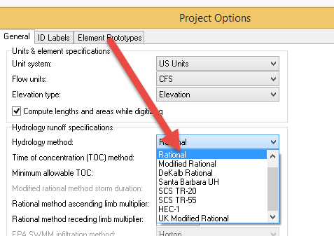
Otherwise, firstly you will need to set your project to a hydrology method that utilizes IFD’s. (‘Merica calls them IDF). Go to Input -> Project Options
Change the Hydrology Method to Rational
Now you need some curve data. Google Search, “Australian IFD data” or go to this link for the bom website. You will need to type in the coordinates of your site. Then you can copy or download the data as a CSV.
…
“IDF” curves in SSA are formatted with the AEP or “Year Return Values” as the rows and min. duration as the columns so you will need to transpose your data in excel. Quite easy, select it all and then rightclick -> paste special -> transpose
You will then need to import this into SSA. I have saved you some time here, you can download the default format here. (this arranges the AEP/duration columns correctly.
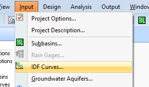
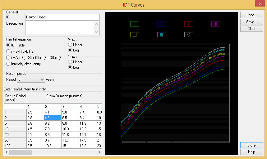
Go to Input -> IDF curves
You will want to load my “Australian IFD Format.idfdb” file (see download link here) so that is structures the AEP/duration correctly.
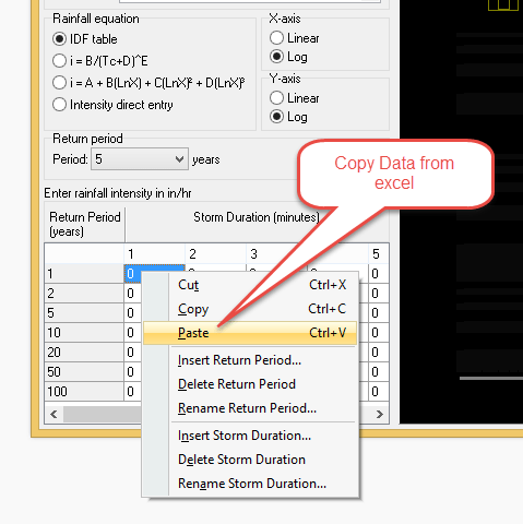
Now just copy/paste the duration data from excel into the little panel down the bottom.
You should now be able to see your curves you can use for analysis
Too many style dependent layers are so annoying in Civil 3D. So many of the styles I am not even using yet the layers still persist.
Wouldn’t it be nice if we could only see the layers of styles that are been used by civil 3d objects. I imagine there could be a setting called STYLELAYERINITIALIZATION
Setting it to 0. Would display all style layers even if there not been used by Civil 3d objects.
Setting it to 1. Would display only style layers in use by Civil 3d objects.
This would be so useful. Been able to save the styles you have selected for various civil 3d objects. In particular, for more complex projects, where constantly resetting between various styles can be rather tedious.
This workflow could even flow over to data shortcuts. Where it would be possible to create reference to multiple objects using the “style states” saved in your project.
Be awesome if all of the build definitions where exposed to the regular autocad properties window. This would allow angle/length to be changed on multiple surfaces at once!
Maybe even the operation build order could be exposed when you have once surface selected?